AMSAT Oscar 40 - the ultimate amateur satellite
Latest infos
For most recent and detailed infos take a look at the AMSAT-DL Journal
Receiving and transmitting capabilities of AO-40
You can call it a super satellite without exaggeration having in mind the datas of the TX/RX components:
|
Uplink (MHz) |
Downlink (MHz) |
|
21.210 - 21.250 |
-- |
|
24.920 - 24.960 |
-- |
|
145.840 - 145.990 |
145.805 - 145.955 |
|
435.550 - 435.800 |
435.475 - 435.725 |
|
1269.250 - 1269.500 |
-- |
|
1268.325 - 1268.575 |
-- |
|
2400.350 - 2400.600 |
2400.225 - 2400.475 |
|
2446.450 - 2446.700 |
2401.225 - 2401.475 |
|
5668.550 - 5668.800 |
-- |
|
-- |
10451.025 - 10451.275 |
|
-- |
24048.025 - 24048.275 |
Working downlinks are black. The HF antennas are mounted under the solar panels so can be used only when these are unfolded. That's when 3 axis stabilisation is in action.
The transmitters do have the following output power (PEP):
|
145 MHz |
100 W |
|
435 MHz |
150 W |
|
2400 MHz |
50 W |
|
10450 MHz |
50 W |
|
24048 MHz |
1 (20) W |
AO-40 Telemetry Beacons
|
BEACON |
General Beacon (GB) |
Middle Beacon (MB) |
Engineering Beacon (EB) |
|---|---|---|---|
|
2 m |
none |
145.898 MHz * |
none |
|
70cm |
435.450 MHz |
435.600 MHz |
435.850 MHz |
|
13cm(1) |
2400.200 MHz |
2400.350 MHz |
2400.605 MHz * |
|
13cm(2) |
2401.200 MHz |
2401.323 MHz * |
2401.600 MHz |
|
3cm |
10451.000 MHz |
10451.150 MHz |
10451.400 MHz |
|
1.5cm |
24048.000 MHz |
24048.150 MHz |
24048.400 MHz |
* - actually heard frequency
Working AO-40
Receiving
The usable bands at the moment (Aug. 2001)are 70/23cm for uplinking and 13cm for the downlink. Meanwhile we gain another downlink band: 24 GHz. This leads to the following modes:
U -> S
L -> S
U -> K
L -> K
Since February 2003 the S1 uplink is tested and confirmed working. So the mode S -> K is operable, basically.
The 24 GHz downlink is at the moment (14. Nov. 2001) active from MA 118 - 138 in parallel to the S-Band. For more update information see AMSAT-DL Journal.
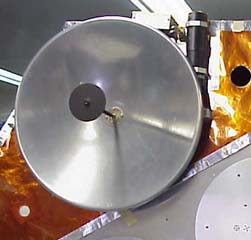
Unfortunatelly one of the two downlink transmitters, the S1-TX failed after a few weeks of operation. This is a pity because it provided superior signals, compared to the S2-TX, which will be the main downlink for the future. The antenna of S2 is a 5 turn helix with a gain of 10.5 dBi built by Freddy, ON6UG. The additional 9dB of the S1 dish antenna are missed strongly...
Although the S2-TX is running 50 W, the effort to receive should be at least a small dish antenna. Helical antennas aren't sufficent for a solid copy.
To give a solid information:
The beacon is about +33dB above the transponder noise floor. This means a possible 23dB dynamic range for signals. If you can here the transponder noise floor you can't further improve your receiving system anymore. (well you can get a bigger receiving antenna (read: dish) to get the noise floor at bigger squint angles , but if you don't just want to see transponder noise floor at 'S9+' you can stopp improving the RX chain when you hear the noise floor.
 |
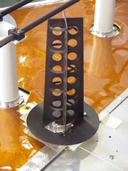 |
| AO-40 S1 dish antenna | AO-40 S2 5 turn helix antenna |
System noise figure
If you like to determine your overall system performance you have to include all components with their individual losses and noise figures. This has been done already by Gene Marcus, W3PM/GM4YRE with a very flexible Excel spreadsheet. Download the AO-40 Groundstation Evaluation Tool or go to the original site of Gene..Play around with the numbers and see where the most sensitive stage is. You will see the first active stage will determine the overall system performance. Is it low noise and gives enough amplification the rest of the RX chain is of very marginal influence.
Hearing the beacon
The S2-Middle Beacon is in general 10dB louder than any other signal on the transponder passband. So get the doppler correction for the actual satellite position (f.e. with the help of SatPC32, a very helpful programm) and try to listen to the 400bps signal. If you are able to hear the beacon 10 - 15 dB above noise you can look out for transponder signals. CW signals may appear earlier in the noise, SSB is a bit harder (needs at least 6 dB better signal to listen to with not to much pain)
Decoding the 400 bps BPSK of the Middlebeacon
M QST AMSAT OSCAR-40 2001-11-14
ALON/ALAT = 3/0, Orbit 478, station keeping with torquer.
*** See N-block for schedule. NOTE: K-Tx passband ***
*** Middle Beacon OFF: MA 70-87 ***
The AO-40 team would like your telemetry files!
Please "zip" compress your daily telemetry files and e-mail to:
ao40-archive@amsat.org
N QST AMSAT OSCAR-40 ***SCHEDULE S2 Downlink*** 2001-11-01
Listen to the transponder passband
Now if you were able to listen successfully to the beacon try to hear some QSO activities on the transponder passbands. There are always some strong signals on the downlink which you can hear even with modest listening capabilities. But if these are near the beacon level or even higher don't expect a regular signal is as loud as these ones ! Station that loud violating the operation recommendations of the command team. They desense the RX of the satellite and induce other users to turn up their power. An even higher AGC level is the result. If you can't get other staions than the ones running at beacon level you need definately a better receiver !
Practical antennas
At the moment running spin stablization there are minimum requirements for a reliable downlink signal. Due to the higher than original planned apogee of ~65.000 km and the not activated three dimensional attitude control some off pointing of the used antenna (helix) leading to lower signals as expected. So a 16 turn helix with a good (low noise with NF <1dB ) PreAmp/Converter with sufficent gain are required at minimum. But don't expect more than a barely useable system, especially when listening to the transponder passband or near apogee. If you have to use a (single) helix go for the longest reasonable length ( ~ 7 lambda, see:helix experiments de Scott, NX7U). A small dish of at least 45cm diameter will improve the situation remarkable (use a 60 cm solid dish and a low noise first active stage of <1 dB NF for comfortable reception).
If you are willing to do alot of mechanical work and use some good quality components you can try to copy that quadruple helix array of Howard, G6LVB. It will give you near the performance of a 60cm dish, but for a lot of more work and money than a dish!
At the moment I am using a 60 cm prime focus dish. The feed is a 2.5 turn helix (2.25t with 0.25t matching section). Hope some pictures will be published soon. Meanwhile you can watch the same dish I am using at the QTH of Michael, DH5MK.
A very nice portable S-Band receiving station was built by Achim, DH2VA. This size is all you need if you use low noise components (converter and/or preamplifier).
Transmitting
First of all: Always keep your signal 8 - 10 dB below the satellites beacon level !
U-band - 70cm
So far the experience of users show that you will need abt. 100 - 300 W EIRP to make it through the transponder. You can try a linear antenna but RHCP (right hand circular polarization) make things easier. The problems is that seems to be only theoretical, not because of the basic satellite capabilities but there are too many users running too much power on the uplink ! The AGC of the uplink is sometimes in the 20's ! So 15 to even 25 dB of attenuation is hardly to compensate. See the telemetry analyses of Lee, KU4OS.More than 50% of the time 7 dB of AGC level is in action forcing the user to run 5 times more power than required. Unfortunately LEILA can't notch all the big signals at the same time and leaves out some sorts of signals (SSTV, CW)
Take a look at the antenna site de Jerry where you can find a 70cm cross yagi among many other satellite projects. All antennas are homebrewed, especially designed for Phase 3D, giving you a good starting point even for space limited QTHs.
Howard, G6LVB has succesfully copied a 70cm cross yagi, originally designed by Kent, WA5VJB and published by the Clear Lake Amateur Radio Club.. These yagis are pretty easy to copy, use common available materials and reduce the comlexity of the feed. They do have great bandwidth and pattern and fair gain. A good project for beginners in homebrewing yagis.
L-band - 23cm
Here is a power of 500 - 600 W EIRP needed. I heard Domenico, I8CVS operating L/S. He is using 4 times 23ele yagis (horizontal polarized). When running 20 - 8 W he was loud and clear. Below that his signal starts getting weak (receiver here was a 60cm prime focus and 1,7dB NF)
My antenna for AO-40 2m-band
Not anymore for AO-40 but still useful
The goal to keep the antenna as small as possible leads to optimized, well designed antennas to get the most out of the used boomlenght. Smaller boom lenght and the request of high gain results in a low feed impedance. But the price is often a terrible pattern and poor F/R relation. So I've chosen a compromise of gain, bandwidth and still useful pattern (F/R) with this DK7ZB design.
| Elements |
lenght(free space 6mm elements) [mm] |
lenght(free space 10mm elements) [mm] |
|
R |
1010 |
1040 |
|
DE |
953 * |
953 |
|
D1 |
939 |
932 |
|
D2 |
920 |
908 |
* DE always 10mm !
The electrical datas (at 145 MHz) with AO 6.59 de K6STI
-
Gain: 9.04 dBi
-
F/R: 14.7 dB
-
Impedance: 28 Ohm
-
Azimuth beamwidth: 58°
-
Elevation Beamwidth: 83°
See the vertical and the horizontal pattern at 145 MHz done with AO 6.59 de K6STI.
Compared to the 3ele yagi of same boom length it is a plus of 0.8 db gain and a loss of 6 dB in F/R. But still the antenna covers the whole IARU Region 1 2m band 144 - 146 MHz with a SWR of 1:1.3 or less (like all my short yagis do).
For the most efficent use of these short antennas working AO-40 especially at the apogee linear polarization should be avoided. As AO-40 provides a clean circular polarized signal you can overcome the -3db signal loss due to the wrong polarization and use fixed (right handed)or switchable (RHCP/LHCP) circular polarization.
All these 28 Ohm impedance yagis can also be feed with a folded dipole giving a 4:1 tranformation and put 2 of them together resulting in a 56 Ohm final impedance.
|
last update: |
Home |