A High Gain Mode J/B Yagi Antenna
Operating satellites portable is often limited by a lack of electrical power. If you want to improve your signal (up- and downlink) you have to do it with the help of a gain antenna. I choosed 2 designs of DK7ZB due to their low weight and good efficency. The boom is a square aluminium tube 20 x 20 x 1 mm to give a certain strongness with still handy dimensions.
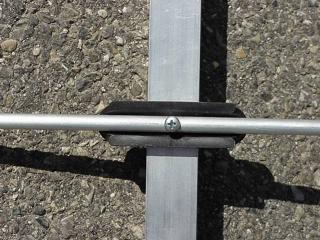
To keep the mutual influence as low as possible the 2 yagis are mounted in different planes. Maybe it is also posssible to do it in the same plane using short antenas like here. The elements are dismantable to keep it portable (important for 2m part). All parasitic elements consisting of 6mm aluminim tube to save weight and still have a good stability. The fastening used are commercially availible element holders of UV-stabilized polyamid. Look at the picture below for details.
In avoiding all the problems of baluns (mechanical and electrical) in cross yagis, I followed the statements of Graham, F/G8MBI about DE and used a straight, split dipole with direct feed connection. Especially in thus case with a limited boom length the antenna elements must be located at an certain area to keep it still portable and a cable balun already can cause at least mechanical difficulties due to the cross yagi character of this antenna.
 fixing of
parasitic element
fixing of
parasitic element
The 70cm yagi
The actual design was choosen mainly because of its broad 50 Ohm characteristics, nice gain and still handy dimensions of 1m boom length. The diagramm is also pretty good. This 70cm part of the antenna give you a very good signal also on terrestric use, improving the range of your handheld TRX drastically. Likewise as a single 70cm-sat-downlink antenna a good choice.
The electrical datas (free space at 435 MHz):
-
gain: 12,89 dBi
-
F/R: 17,74 dB
-
Impedance: 50 Ohm
-
azimuth bandwith: 42 °
-
elevation bandwith: 47 °
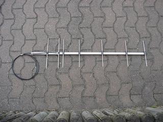 a first prototype
| Elements |
position [mm] |
free space lenght [mm] |
free spacehalf lenght [mm] |
|
R |
0 |
333 |
166,5 |
|
DE |
115 |
328 |
164 |
|
D1 |
160 |
303,5 |
151,75 |
|
D2 |
320 |
297 |
148,5 |
|
D3 |
555 |
290 |
145 |
|
D4 |
800 |
289 |
144,5 |
|
D5 |
995 |
290 |
145 |
Take a look at the horizontal and vertikal diagramms done by AO 6.59 de K6STI.
Mechanical construction
Parasitic elements
The material is 6mm aluminium tube. You do a raw cut with the saw and use the file for the last precision. The elements were hold in place by 3 x 35mm screw (stainless steel if posssible) in the center.
Driven element (DE)
The driven element just consists of a straight split dipole. Due to the broad 50 Ohm characteristics a direct connection of the feeding line is possible. With ring lugs and stainless steal screws the coax cable is connected to the two legs of the dipole. As the parasitic elements the dipole is isolated with the same polyamid holder (plates of PVC and Plexiglas®/Makrolon are also possible).
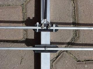 closeup
feedpoint (first testing)
closeup
feedpoint (first testing)
The above measruement of DE give me a resonance at 446 MHz So the actual lenght of DE must be prolonged. That is the only tuning that is needed ! Nevertheless receiving satellites was no problem at all and transmitting with local hams also was possible with HT. For the final DE I am using a 10mm alu tube due to better mechanical handling.
Symmetric element and unsymmetric feed
It is possible that some problems occure when you are transmitting with P > 5W. There will be some currents on the braid of the coax that can influence the resonace of the antenna in a very negative way. The whole thing is getting extremly touchy and a final tuning of DE is (almost) impossible.
To overcome these problems you can spend a balun or you can ground the coax to the boom at lengths of lambda/4. For a portable version you have to use an isolated hold to avoid unpredictable coupling effects originating from the presence of your body (nearly unavoidable).
Performance
The difference between the 'Handitenna' de K5OE and this yagi is quite substantial, especially if the satellite is near the horizont and signals are weak. You can track the satellite until it is disappered below horizont. So all LEOs (AO-27, UO-14, SO-35, FO-20, FO-29) are received reliable.
Version 2
As mainly constructed for portable use the next version was built with 15 x 15 x 1mm aluminium square tubing that gives a substantial save of weight. Also the boom was prolonged to have a more balanced antenna with some weight at the very end of the hold. Still the antenna is full aluminium to allow every time an outdoor operation. The DE is now 10mm and in the portable version also hold by the same polyamid holders as the parasitic elements. In an alltime outside version the DE can be enclosed in a box. The two legs of the dipole are isolated with a hard PVC rod.
The 2m yagi
In avoiding additional work I chose a pure 50 Ohm design for the 2m part also. Although the 28 Ohm version provides better gain the work of producing a precisely cable balun can be avoided and simplifing the mechanichs in a 'cross' yagi. Giving up some gain (1.3 db to be exact) is not that dramatic as it sounds. The result is a very broad, mechanically tolerant antenna you are able to fabricate in a shorter time in avoiding some more work in potentially lossy and defective parts not necessarily needed.
The electrical datas (free space at 145 MHz) by AO 6.59 de K6STI:
-
gain: 6.9 dBi
-
F/R: 19.7 dB
-
impedance: 50 Ohm
-
azimuth bandwith: 68 °
-
elevation bandwith: 124°
The mechanical datas
| Elements |
position [mm] |
length [mm] free space |
half length [mm] |
|
R |
0 |
1044 |
522 |
|
DE |
470 |
979 |
489,5 |
|
D1 |
750 |
878 |
439 |
Mechanical construction
Parasitic Elements
Aluminium tubes of 6 x 1mm was used to save weight. The tubes are holded isolated on the boom using commercial holders of polyamid by Konni (same like the 70cm part). The tubes are fixed with (preferable) stainless steel screws. Although grounded at the boom the free space dimensions can be used with only neglectible deviation.
Driven Element
A 10 x 1mm aluminium tube was used. The two legs of the split dipole are holded with the lower part of a commercially polyamid holder for (6m)yagis. Alternatively a box can be used like the 2m DX yagi for permanent outdoor use. Inside the tubes a rod of hard pvc was used. The coax is directly fixed with ring lugs.
On the contrary to the 70cm yagi there was no current on the coax braid when testing.
The original computed measurements in the above table was used without any problem. The SWR was very flat from 144 - 146 MHz exactly as modeled.
Take a look a the elevation and the azimuth plot, done by AO 6.59 de K6STI.
The complete VHF/UHFyagi
To minimize mutual coupling the two antennas are mounted in different planes.
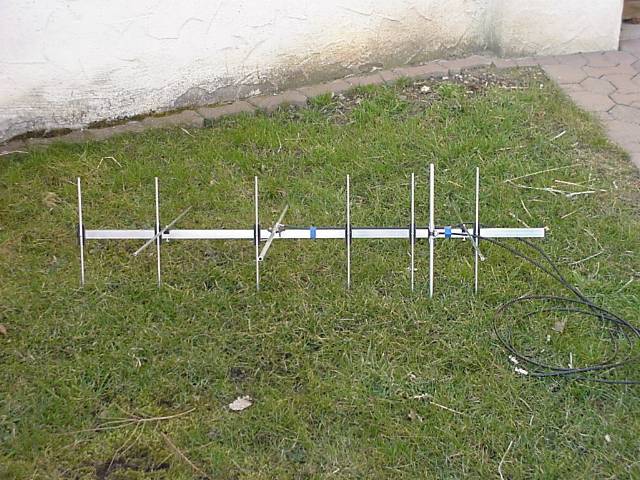
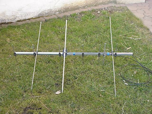
Click on the pictures to enlarge them.
Other VHF/UHF beams
2 DL6WU yagis combined by Alejandro, XE1MEX
A copy of Alejandros ant made from TV-antenna material de Jeff, KK5UFO
A very portable mode j/b beam de Tony, VK3JED
The 3 + 7 ele yagi combination de Mike, KC5JDG
|
last update: |